Belt Drive Selection
Sprocket driven system
- Provide a positive drive of the belt and help
maintain belt alignment.
- Generally lower cost than pulley driven systems.
- Center-to-center sprocket spacing should not
exceed six (6) inches. Sprockets spaced greater
than 6 inches apart can cause premature
belt failure due to excessive strain on the
connecting rods.
- Under heavy load conditions, spacing should
be as close as possible.
- All drive sprockets should be keyed in-line.
- Tail sprockets should have plain bores,
except the center sprocket, which should
be keyed to ensure shaft rotation.
- Plain bore sprockets should be collared
to prevent lateral movement.
Pulley driven systems
- Provide a friction drive, which evenly distributes
the drive tension.
- Does not subject the belt to rod wear.
- Must be run on an accurately aligned conveyor
to prevent tracking problems.
- Use only lagged, flat-faced pulleys

Sprocket Location

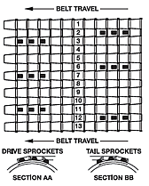
Proper sprocket location is essential for smooth belt
operation. Sprocket teeth must always drive against the
connector rods. Drive sprocket teeth should be in the
odd numbered openings and tail sprocket teeth in
the even numbered openings.
When mounting the sprockets, the long side of the
hubs MUST FACE IN THE SAME DIRECTION. Drive
sprockets cannot be located in the outside mesh
openings in belt specifications S3, S7, H4 and H5.
Never use tail sprockets to power another conveyor. |

Special Features
Hardened teeth
- May be supplied with cast iron and steel sprockets.
- Can increase sprocket life by 2-3 times under
severely abrasive and heavy load conditions.
Bronze bushings
- Can be supplied for tail or idler sprockets to
reduce shaft wear.
- Are press fitted into the sprocket bore.
Cut down hubs
- Available for all sprockets.
- Enable close sprocket spacing on heavy load
applications.
Machining of teeth
- Provides clearance for use with ½" x 1" modified belts.
Square bores
- Keystone can add square bores into plastic
sprockets. Bore tolerance is +0.010",-0.000'.
Set screws are not included but may be furnished
with an additional charge.
Splitting of sprockets
- Most sprockets can be split so the sprockets can be installed without removing the shaft. The bore size may be limited so there is enough room for the bolts to hold the sprocket together. Sprockets with an odd number of teeth are cut on two different angles to avoid splitting the sprocket through the teeth.

Bore Sizes & Keyseats
Keyseats
- Accurate, aligned keyseats of different sizes can
be cut in any sprocket.
- Factory supplied keyways are accurately located
through the use of a jig, assuring uniform tooth
engagement.
Set screws
- All bored and keyed sprockets are furnished
standard with two (2) set screws.
- Standard set screw sizes are listed in the table below. However, Keystone reserves the right to change the size of the set screw without notice.
English Sizes
| Dia. of Bore |
Keyseat |
Set Screw |
| 3/4 to 7/8 |
3/16 x 3/32 |
1/4" |
| 15/16 to 1 1/4 |
1/4 x 1/8 |
5/16" |
| 1 5/16 to 1 3/8 |
5/16 x 5/32 |
5/16" |
| 1 7/16 to 1 3/4 |
3/8 x 3/16 |
3/8" |
| 1 13/16 to 2 1/4 |
1/2 x 1/4 |
3/8" |
| 2 5/16 to 2 3/4 |
5/8 x 5/16 |
1/2" |
| 2 13/16 to 3 1/4 |
3/4 x 3/8 |
1/2" |
| 3 3/8 to 3 3/4 |
7/8 x 7/16 |
1/2" |
| 3 13/16 to 4 1/2 |
1 x 1/2 |
1/2" |
Metric Sizes
| Dia. of Bore |
Keyseat |
Set Screw |
| 23 to 30 mm |
8 x 3.3mm |
8mm |
| 31 to 38 mm |
10 x 3.3mm |
10mm |
| 39 to 44 mm |
12 x 3.3mm |
10mm |
| 45 to 50 mm |
14 x 3.8mm |
10mm |
| 51 to 58 mm |
16 x 4.3mm |
12mm |
| 59 to 65 mm |
18 x 4.4mm |
12mm |
| 95 to 110 mm |
28 x 6.4mm |
12mm |
|


