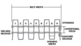
Belting Technical InformationFlat Wire Belt Materials
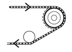 Belt WrapKeystone recommends that the maximum belt wrap on drive sprockets be limited to 150o. Belt wrap of more than 150o could resist releasing from the sprocket and continue a full revolution around the sprocket, damaging the belt. For tail sprockets, the maximum wrap is not as critical, but should be limited to 180° or less. Belt Identification Process
DRIVE TENSION CALCULATIONS FOR STRAIGHT RUNNING BELTS
|
|||||||||||||||||||||||||||||||||||||||||||||||||||||||||||||||||||||||||||||||||||||||||||
| Td = Drive Tension (lbs.) WB = Weight of Belt (lbs/ft2) WL = Weight of Load on Belt (lbs/ft2) |
F = Friction Factor (see Table, below) B = Belt Width (ft.) L = Conveyor Length (ft.) (1/2 the belt length) |
ELEVATED TEMPERATURE (F) vs. STRENGTH
| 500 | 600 | 700 | 800 | 900 | 1000 | 1200 | 1400 | |
|---|---|---|---|---|---|---|---|---|
| Galvanized Low Carbon |
1.0 | N/A | ||||||
| C1050 High Carbon |
1.0 | 1.0 | 0.9 | 0.3 | N/A | |||
| T-201 Stainless Steel |
1.0 | 1.0 | 1.0 | 0.65 | N/A | |||
| T-304 Stainless Steel |
1.0 | 1.0 | 1.0 | 0.8 | 0.75 | 0.7 | 0.5 | N/A |
| T-316 Stainless Steel |
1.0 | 1.0 | 1.0 | 0.85 | 0.8 | 0.75 | 0.65 | 0.5 |
FRICTION FACTORS BETWEEN BELT & BELT SUPPORT
| Belt Support | Friction Factor |
|---|---|
| Ball Bearing Rollers | 0.10 |
| Sleeve Bearing Rollers | 0.15 |
| Plastics Faced Slider Bed | 0.20 |
| Steel Slider Bed - Lubricated | 0.30 |
| Steel Slider Bed - Unlubricated | 0.35 |
Sprocket Selection
To calculate the minimum number of drive sprockets for
a conveyor system:
The larger of the two numbers is the minimum number of sprockets needed. Spacing of tail or idler sprockets should be between 6" and 9". Never exceed a drive sprocket spacing of 6 inches, even for light loads. |
|
||||||||||||||
Internal Welds
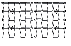
All welded selvage belts over 24 inches in width feature the resistance welding of every other connector rod to the flat strip on the 2nd opening in from each edge of the belt. On True 1/2" x 1/2" mesh belts this weld is on every 3rd connector rod.
This provides for greater strength and eliminates belt shrinkage under heavy loads without restricting flexibility of the belt.
Upon special request, belts 24" and under can be supplied with internal welds.
COMPARISON OF FULL SCALE FLAT STRIP & ROD SIZES

Belt Tracking
The belt length to width ratio should be no less than 5:1 as tracking problems are more likely to occur with wide belts which have a short length. Using alignment guides on the edges of a flat wire belt can cause premature wear.
Since the majority of belting problems are alignment related, it is extremely important to have all shafts parallel to each other and perpendicular to the conveyor bed. If a good alignment is not completed before using a flat wire belt, longitudinal pitch can be distorted causing the belt to track to one side. Improper handling of the belt before and during installation can also damage the belt creating alignment problems.
The best way to track a flat wire belt is to use several adjustable support rolls located on the return side of the conveyor just before the tail shaft. These rolls are skewed either forward or backward, on a horizontal plane, to track the belt.
Belt Assembly
Belts are supplied with an additional connector rod for each 10 feet of belting. To splice sections, or to create an endless belt, bring the two ends of the belt together and insert a connector rod. Standard duty, clinched selvage connector rods are supplied with a preformed hook on one end and straight wire on the other. With pliers, close this hook and form a similar hook on the opposite side. Welded selvage and heavy duty connector rods are supplied with a button head weld on one end, and a thread nut on the other end. Tighten the nut and cut off any excess rod. Rod end threads should be distorted to secure the nut.


